

Next: Branching and Spatial
Up: Radiation and Simple
Previous: Gain Due to
More generally, a fractal tortuous path can also be constructed in terms of
a random walk between two endpoints [Vecchi, et al., 1994]. We
start with a straight line of length L, to which the midpoint is displaced
using a Gaussian random generator with zero average and deviation  (usually
  ). The procedure is then repeated to each of the
straight segments N times. There is a clear repetition in successive halving
of the structure as we go to smaller scales, making this antenna broad band.
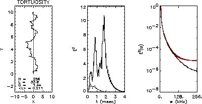
Figure 6a shows a typical tortuous fractal where the division
has been taken to the N=8 level and in which the pathlength s has increased
5 times, i.e. s=5L. We can estimate the fractal dimension by realizing
that the total length should go as
  , where
  is the
average segment size. This formulation is completely equivalent to Eq. (1).
We let an oscillating current, e.g.  propagate along the
fractal, but in real applications we can imagine the oscillating current
lasting for only a finite time
  . In order to have a finite
current pulse propagating through the fractal random walk, we let
  with
with  and
and  as the step function. Here n
 represent the number of oscillations during the decay time scale 1/
 . We chose the decay parameters as
  s
s and
and  s
s , hence
  , which correspond to
realistic parameters for lightning [Uman, 1987]. The radiated power
density is then computed using Eq. (12) and is shown in Fig. 6b for n
 and
and  at the position a
 , a
, a
 km. The dipole equivalent is given by the dashed lines in all 3
panels. The peak in the radiated power density is about 10 times larger than
for the dipole case, which agrees well with the results
 n
n even though the effect from the tortuosity is not
small. The larger path length of the tortuous discharge produces an increase
in the radiation as compared with a dipole radiator. Of course there is a
limit due to energy conservation, but in practical applications we are well
under it. The increase in the high frequency components of the radiated
field power spectrum (Fig. 6c), as compared with the dipole
antenna, will be responsible for the spatially structured radiation pattern.

Figure 6: The fractal random walk (a) and its instantaneous radiated power
density (b) as well as its power spectrum (c). The dashed lines represent
the behavior of the single dipole.
The far field array factor  (defined in
Appendix A) and the peak power density depend on the path length, or
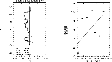
equivalently on the number N of divisions of the fractal. Figure 7b shows the array factor as a function of the path length for the
fractal shown in Fig. 7a. Here n
 so that the peak of the
array factor is at a
 and a
and a . There is a clear increase in the
array factor from the tortuous fractal as compared with the single dipole.

Figure 7: (a) The tortuous discharge. (b) The array factor dependence,
normalized to the dipole, on the pathlength.
Therefore, the effect of tortuosity can increase the radiated power density
at certain locations as compared to a single dipole antenna.
Another important concept related to fractal antennae is the spatial
structure of the radiation field. We can see from the array factor, Eq. (13), that for large n
 . The spatial dependence of the array factor will be
determined by the factor
  over the fractal.
Consequently, the radiation pattern will have spatial structure when
  which translate into n
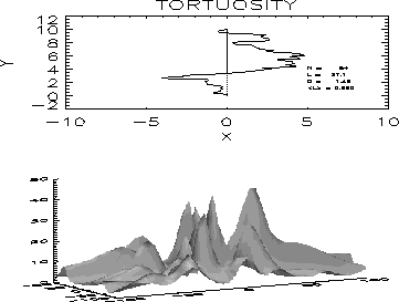
 . Figure 8b shows the array factor at the height h=60 km for the discharge
structure shown in Fig. 8a with n
 . Therefore, such a
tortuous fractal can also display a spatial structure in the radiation
pattern. But it is more natural for the spatial structure to be generated
through a branching process as we will see in the next section.

Figure 8: The fractal structure (a) and its array factor(b) showing clear
spatial structure in the radiation pattern.
There is an energy constraint that limits the degree of tortuosity of a
fractal lightning discharge since we cannot radiate more energy than what is
initially stored as separated charge. Also, if the line elements of the
antenna given by Fig. 5 get too close together, then their
contribution to the radiated field will tend to cancel each other.
Therefore, there is an optimal number of elements forming an antenna, and
this optimal number translates into an optimal dimension of the fractal,
more on this later.


Next: Branching and Spatial
Up: Radiation and Simple
Previous: Gain Due to
 (usually
  ). The procedure is then repeated to each of the
straight segments N times. There is a clear repetition in successive halving
of the structure as we go to smaller scales, making this antenna broad band.
Figure 6a shows a typical tortuous fractal where the division
has been taken to the N=8 level and in which the pathlength s has increased
5 times, i.e. s=5L. We can estimate the fractal dimension by realizing
that the total length should go as
  , where
  is the
average segment size. This formulation is completely equivalent to Eq. (1).
 propagate along the
fractal, but in real applications we can imagine the oscillating current
lasting for only a finite time
  . In order to have a finite
current pulse propagating through the fractal random walk, we let
  with
with  and
and  as the step function. Here n
 represent the number of oscillations during the decay time scale 1/
 . We chose the decay parameters as
  s
s and
and  s
s , hence
  , which correspond to
realistic parameters for lightning [Uman, 1987]. The radiated power
density is then computed using Eq. (
 and
and  at the position a
 , a
, a
 km. The dipole equivalent is given by the dashed lines in all 3
panels. The peak in the radiated power density is about 10 times larger than
for the dipole case, which agrees well with the results
 n
n even though the effect from the tortuosity is not
small. The larger path length of the tortuous discharge produces an increase
in the radiation as compared with a dipole radiator. Of course there is a
limit due to energy conservation, but in practical applications we are well
under it. The increase in the high frequency components of the radiated
field power spectrum (Fig.
 (defined in
Appendix A) and the peak power density depend on the path length, or
equivalently on the number N of divisions of the fractal. Figure
  so that the peak of the
array factor is at a
 and a
and a . There is a clear increase in the
array factor from the tortuous fractal as compared with the single dipole.


 . The spatial dependence of the array factor will be
determined by the factor
  over the fractal.
Consequently, the radiation pattern will have spatial structure when
  which translate into n
 . Figure
  . Therefore, such a
tortuous fractal can also display a spatial structure in the radiation
pattern. But it is more natural for the spatial structure to be generated
through a branching process as we will see in the next section.
