 ,
as
,
as
Another element in understanding fractal antennae is the concept of
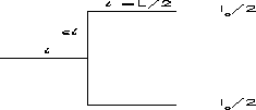
branching. Take the simple branching element shown in Fig. 9
where the current is divided between the two branching elements. We can
compute the radiation field, for a propagating current I ,
as
,
as
where  and
and  is the variation from the single
dipole, i.e. we recover the dipole as
  .
.

Figure 9: A simple branching situation in which we distribute the current
among the branching elements.
Again, the analysis can be simplified in the limit for small  ,
i.e.
  . Of course P(0) is the dipole contribution, and
  is the change in the radiated power
density due to the line branching. The dipole has a maximum in the radiated
power density
  , while
the branching contribution goes as
  . The function f depends on the given parameters, but
its maximum is of the order
  with clear regions in
  where it is positive. Therefore, the branching process can give
rise to an increase in the radiated power density at certain position. Of
course this increase is due to the increase in the path length. This effect
will saturate as
  is increased passed one, since then the
strongest contribution will come from the dipole radiator given by 2
 .
.
A interesting and manageable broadband antenna can be described in terms of
the Weierstrass functions [Werner and Werner, 1995]. We take
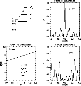
successive branching elements, as shown in Fig. 10a, where we
distribute the current at each branching point so that the branching element
keeps a fraction  of the current. The n
 branching element is
displaced by a factor
  with respect to the origin. If we
concentrate only on the contribution from the last branching set, as shown
in Fig. 10a, we can write the field as


where we have redefined  and a
and a . In the limit
  and N
and N we
obtain the Weierstrass function that is continuous but not differentiable,
i.e. is a fractal, and furthermore, its dimension in the sense given by Eq.
( 1) is d
 . For the purpose of illustration we truncate the
above sum to N=8. In Fig. 10b, we show the dependence of the
field as a function of
  with a
 for
for  . The parameters values are shown in the figure caption.
Figure 10c shows the gain factor given by

as a function of the dimension  . We chose this range
since the fractal already has a dimension 1 in the perpendicular directions,
i.e. D=1+d
 .
.

Figure 10: The branching process to produce a Weierstrass radiation pattern.
(a) The brunching process with the branching length increasing as  and the current decreasing as
  . (b) the
radiation pattern with
  given perfect coherence.
(c) The gain vs the dimension. It also contains the parameters used in all 3
figures. (d) Patial coherence for
  .
.
Note the increase in the gain as a function of dimension. In general, there
is an optimal value of D that generates the highest power density and that
does not necessarily has to be for D=2. In Fig. 10b all the
elements from the antenna add up coherently at  , hence providing
perfect coherence. For a finite
  the propagation brings a
different phase shift at each element. Figure 10d shows the
effect for
  as a function of
  . Note that at no point
there is perfect coherence, but there is clear partial coherence. The peak
value of E
 is actually sensitive to
  .
.
Even though fractal antennae naturally lead to the concept of an increase in the peak radiated power, it also has a second important consequence due to branching. As we have seen in the case of the Wiertrauss function, fractal antennae naturally result in the generation of a spatial structure in the radiated power density. This interplay between the spatial structure and the increase in the peak radiated power are the essential ingredients of fractal antennae and why they are so important. A clear example can be illustrated in Fig. 10d where there are multiple relevant peaks of the radiated power in space.